PATHLOSS 4.0
DIFFRACTION MODULE
This module should never have to be used as links should not be designed that are obstructed. If however, there is no alternative a link can be designed that is obstructed, provided that the diffraction loss does not exceed 25% of the fade margin at Kmin.
Select Module – Diffraction Loss. The Diffraction Loss Module is displayed.
To draw the Fresnel zones press F2, the Fresnel Zone option box is displayed. Select how you want the Fresnel zones to be displayed and press Draw. Close the Fresnel Zone option box when you are finished.

1. Calculating Diffraction Loss
Set the value of K to 1.33 using the K dropdown menu at the top of the screen. If the path is obstructed then the link should be rejected and an alternative route found.
Set the value of K to Kmin using the K dropdown menu at the top of the screen. To do this you may have to edit the K list. Click on Configure – Edit K List, a list of default K values is displayed. Edit this list to include the Kmin value for the link. Close list when done.
Press F9 to calculate the Diffraction Loss of the link. Click on the Tick on the report to accept the values. If the value exceeds 25% of the fade margin the link should be rejected and an alternative route found.
Select Modules – Worksheet. You will be asked if you want to include the diffraction loss in the work sheet. If the link is to be implemented the value should be included in the worksheet.


Reflections can cause the degradation of the received signal on a microwave link depending on the amplitude of the signal and the phase delay at which it arrives. If the reflected signal delay is greater than 20 – 40 nanoseconds, performance problems on high capacity systems can occur unless the reflected signal amplitude is at least 40 dB below the direct signal. Reflection analysis should be carried out in both direction of the link.
Select Module – Reflections, the Reflections Worksheet is displayed.
Defining the Reflective Plane
Select Define Plane and the Define Reflective Plane Worksheet will be displayed.
To define one end of the plane place the arrow to the desired position on one side of the profile and press F1 the arrow will change color. Next place the arrow at the desired position at the other end of the profile and press F1 the arrow will change color and reflection symbol will appear on the profile where the reflection will occur. Click the OK button to accept the reflective plan

2. Modifying Terrain Roughness
Select Modify –Roughness and the Terrain Roughness Worksheet is displayed.
Select Fresnel Zones and draw 100% Fresnel zone to the reflection point. Close the Fresnel Zone options box. Place the arrow at one end of the area covered by the Fresnel zone and press F1, move the arrow to the other end of the Fresnel zone and press F1 again. The terrain roughness of the area will be calculated. Press OK to accept the value.

3. Modifying reflection Parameters
The reflected signal will be attenuated by ground cover so this value should be included in the calculation. Select Modify – Parameters, the Modify Reflection Parameters dialog box is displayed.
The terrain roughness previously calculated and the antenna 3 dB beam width has entered in the form ground Cover – Clearance Loss can be entered. This can vary between 0 to greater than 15 dB depending on the ground cover. The PL 4 manual suggests the following values:
0 to 1 dB Water, desert or salt flats
1 to 3 dB Fields with low vegetation or low grass
3 to 6 dB Sage bush, field with high vegetation or high grass
8 to 15 dB Partially wooded areas including trees along the road which are perpendicular to the path
>15 dB heavily wooded areas
Tick the Use Divergence box. Divergence is the scattering of a reflected signal due to the curvature of the earth. Click OK

4. Varying Parameters to see the Effect of reflections
Select Variable, a drop down menu is displayed and a number of parameters can be varied. For this example Earth Radius Factor (K) will be used.
Select Earth Radius Factor (K), a dialog box is displayed in which the parameters of the calculation can be edited. Once you have completed editing them press OK and a graph showing the effect of Earth radius Factor (K) will be displayed.


5. Dispersion Report
Select Dispersion and the Dispersion Analysis Report will be displayed.
The two most important items on this report are: Reflection Loss and Reflection Delay. The Antenna Heights and Earth Radius Factor (K) can be edited and the result of the changes will be reflected in the report. Once you are finished editing the report press OK.

Unless reliable atmospheric data is available this module cannot be used with any accuracy. The Multipath module displays ray traces for various atmospheric gradients.
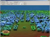
Select Module – Multipath and the Multipath Worksheet is displayed.
The display above shows reflected ray as well as the ray trace for a constant gradient atmospheric scenario.


0 komentar:
Posting Komentar