PATHLOSS 4.0
(English Version)
Download Pathloss 4.0 Update Here
Download Pathloss Tutorial here
3.1 Rain Regional Setting
When radio communications network designed Line of sight, the main thing noticed was the addition of the signal attenuation due to rain. The addition of this signal attenuation occurs at a total loss of transmission lines that use the media not guided ( used air media). Before discussing the method of calculation of these losses is necessary to a discussion of information about the rain issue. Then rain units are expressed in millimeters per hour. Before the implementation of network, designers networks must be able to predict the possibility that will occur in loss-free channel. Usually recommendations for rain area is often used by ITU-R Pn.837-1. Where the division is divided into areas A through Q.

Figure 3.1 Regional Distribution According Rain Pn.837 ITU-R-1
On this rainy region following the distribution according to ITU-R Pn.837-1 which is divided into areas A through Q.
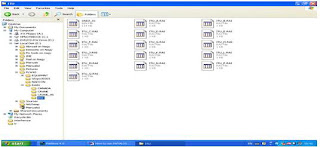
Figure 3.2 Data base Rain zoning of pathloss 4.0
3.2 Topology geography (Terrain view)
The process to enter the terrain data is as follows:
1. Select Configure menu, select the sub menu terrain data base.
2. Select the primary database, content with the choice of available digital maps (in this case is the map SRTM)
3. Press the primary setup
4. Select the file menu, sub menu HDR-BIL-BLW
5. Select the folder where the files are stored SRTM. Further copies of the SRTM data.
Before pathloss can use these data, several parameters must be set first.. The main parameters that need gives a chance is the geographic location of site A and site B. So every site needs to know the coordinates of the nominal value before.
So that necessary steps are:
1. In summary the menu needed to fill the nominal site location data and other general information.
2. Select the terrain data menu, configure the menu the default geographic sub-menu.
3. Select the WGS 1984 datum, elipsoid WGS 84, and the Southern Hemisphere latitude, longitude eastern Hemisphere.
4. Select the UTM grid coordinate system and the second 0:01 nearest second format.
5. Configure menu, sub menu terrain data base.
6. Select the type of digital map on SRTM primarynya, then click the primary setup. Select the file menu HDR-BIL-BLW
7. Find the folder where the SRTM maps are stored, and select Open. Select Close and press the ok button.
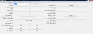 Figure 3.3 Main Menu Pathloss 4.0
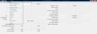 Figure 3.4 Geographic Setting the default
Figure 3.5 Setting a default geographic
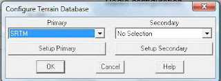
Figure 3.6 Setting terrain data base
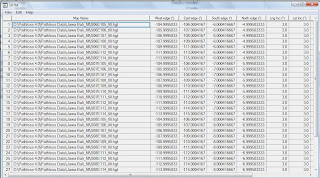
Figure 3.7 Terrain data base using the SRTM
1. Fill nominal data site A and site B on the menu summary.
2. Select menu terrain data, select the menu operation, generate a profile.
3. Fill Increment distance data contents. The smaller the distance value increment, the more detailed information view terrain changes.
4. Press the generate button. Geographical topology automatically between the two sites will appear. Next press the copy button.
5. Further barriers can be added either in the form of trees or buildings between the two points. The Way by double-clicking on the filed structure and select the structure you want to add to the height of the information structure.
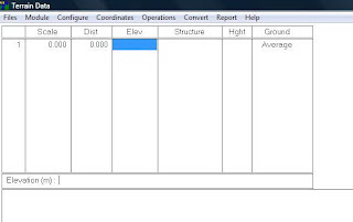
Figure 3.8 Terrain data is not yet filled
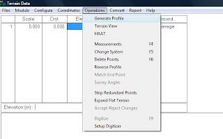
Figure 3.9 Showing terrain view
Terrain view
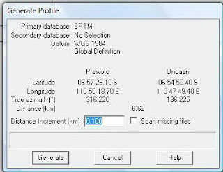 Figure 3.10 Determining the density of Terrain view
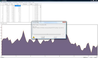 Figure 3.11 Copying Terrain view the pathloss
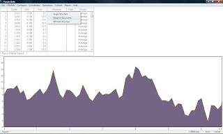
Figure 3.12 Adding the terrain Structure
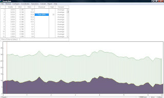
Figure 3.13 Terrain with structure
3.3 Determining the Minimum Antenna Elevation
The stages to determine the height of the antenna are as follows:
1. Select the menu Antenna heights.
2. Click the Optimize button (image button calculator) to get the optimum height of the antenna is required.
3. To determine the height of the antenna itself can be used microwave antenna set menu heights.
4. Fill The contents of the data and an antenna height of tower height to be used for each site on the fields.
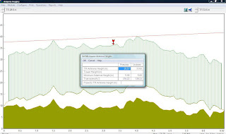
Figure 3.14 Setting up antenna height
The process for displaying site profile path between two points to point is select print menu profile. Automatically reflected terrain conditions, LOS distance between the site, the site elevation, and elevation antenna that gives a chance will draw.
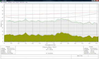 Figure 3.15 Module Print Profile
 3.5 Using the Menu Worksheet
1. Determining the reliability method.
Method for setting up communication channels are as follows:
1.1. Select the worksheet menu, then select the menu operation.
2.2. Select the sub menu options reliability.
3.3. Select the method that will be used reliability, presentation time reliability, calculation methods, the type of radio that will be designed, and standard regions.
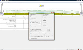 Figure 3.16 Setting up the network reliability
 2. Choosing the rain site data
1. Open Menu worksheet.
2. Click image cloud
3. Select the polarization is used and also local zoning method used rain.
4. Press the Load rain file. Select type of rain areas in accordance with the area where the site will be established.
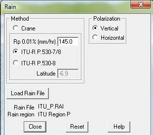 Figure 3.17 Setting up regional polarization and rain
 3. Provide additional information on the state of earth's topography profile
1.Click on image terrain.
2. Menu will display the path to the data profile. Select the menu geoclimatic factor. Select the appropriate terrain classification and also the appropriate humidity areas.
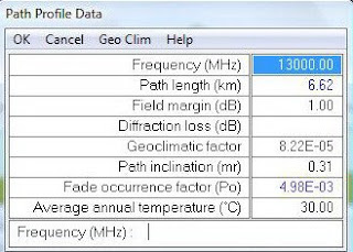 Figure 3.18 Data topographic profile
 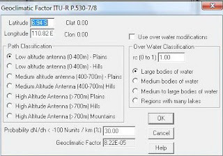 Figure 3.19 Setting geographic factors
 4. Selecting the radio equipment used
2. Click on the symbol TR. Click on the lookup button.
3. Select the radio to be used and press both buttons.
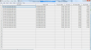 Figure 3.20 Determining the radio to be used
 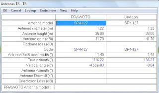 Figure 3.21 Selecting a radio that will be used
 3.6. Choosing antenna used
1. Select the worksheet menu. Click the image antenna.
2. Click the lookup menu, select the antenna that will be used.

Figure 3.22 The information that will be used antenna
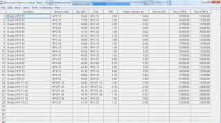 Figure 3.23 Selecting the antenna to be used
 Stage to enter the frequency data is as follows:
1. Select the worksheet menu. Click image ch.
2. Click the lookup menu, select the frequency that will be used.
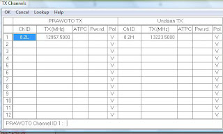 Figure 3.24 Frequency of use
 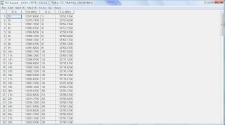 Figure 3.25 Selecting a frequency that will be used
3.8. Showing results calculation
1. Open the worksheet, click the Report menu, select the menu full report.
2. Pathloss 4.0 will fully show the software calculations (link budget calculation).
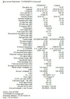 Figure 3.26 Full report


0 komentar:
Posting Komentar